Sensor Data
Sensor data (LiDAR point clouds, camera imagery, trajectory / pose) helps you align and validate the HD map against the physical world. RepliMap expects sensor datasets to follow the folder layout and naming rules below before import.
Sensor Panel Overview
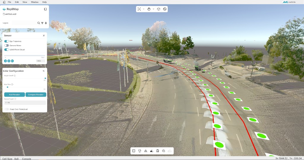
After sensor data is loaded, use the Sensor and LiDAR configuration areas to control what appears in the view:
- Ego trajectory — show or hide the driven path (typically red) over the map or point cloud.
- Camera views — show or hide camera-frame markers along the trajectory (green icons for each captured frame).
- LiDAR point cloud — toggle the .las point cloud in the 3D view.
Use the playback / frame controls (slider and step buttons) to move through frames; the range matches the rows in the job’s metadata CSV. In LiDAR configuration you can adjust height cutoff, max tiles, sensor height (see Road height offset below), elevation actions (Add Elevation, Compare Elevation), and related options so the point cloud lines up with the road model.
The layout groups layer visibility (trajectory, cameras, LiDAR) with playback and LiDAR settings. Sensor height should match your rig; it works together with road height offset so the point cloud matches the road model.
Supported Folder Layout
To load sensor data into RepliMap, organise files under a single root folder you select in the application (below it is called MyDataFolder).
MyDataFolder
├── MyPointCloud.las              # REQUIRED — at least one .las file
└── MyImagesFolder                # REQUIRED — all camera images and metadata
    └── MyImagesSubFolder         # REQUIRED — one subfolder per SphereCam job
        ├── Job_xxxxx_Sphere.csv  # REQUIRED — metadata for the job (one or more CSVs if multiple objects)
        ├── Job_xxxxx_Sphere_000001.jpg
        ├── Job_xxxxx_Sphere_000002.jpg
        ├── Job_xxxxx_Sphere_000003.jpg
        └── …
Mandatory Checklist
- At least one
*.lasfile in the root folder. - An images folder (name can match your app configuration).
- Inside that folder, a job subfolder.
- Inside the job subfolder:
- At least one SphereCam-style CSV (
Job_<JobId>_Sphere.csv). - All
Job_<JobId>_Sphere_*.jpgimages for that job.
Keep folder names stable after tiling
Do not rename the main sensor-data folder or child folders after tiles have been generated. Renaming can break references between tiled data, images, and metadata.
Root Folder (MyDataFolder)
- This is the directory you choose when loading the dataset.
- Must contain at least one LiDAR file in LAS format.
- Must contain the images folder; its name must match what you configure in the application.
Point Cloud (.las)
- Extension:
.las - At least one file is required in the root folder.
- If several LAS files are present, RepliMap loads all of them and breaks the data into tiles for processing and display.
Images Folder (MyImagesFolder)
Contains a single job subfolder for the camera job / capture session.
Image Subfolder (MyImagesSubFolder)
The job subfolder must include:
- One or more CSV files with camera metadata (SphereCam CSV is required for that workflow).
- All JPEG images belonging to that job.
Do not remove or rename individual images relative to the CSV: the application assumes each CSV row matches one image file, and that every image for the job is listed in the CSV.
File Naming
CSV Metadata
Pattern:
Job_<JobId>_Sphere.csv
Examples: Job_01234_Sphere.csv, Job_20241015_Sphere.csv
The <JobId> must be consistent with the image filenames in the same folder.
Camera Images (SphereCam)
Pattern:
Job_<JobId>_Sphere_XXXXXX.jpg
Examples: Job_01234_Sphere_000001.jpg, Job_01234_Sphere_000002.jpg
The <JobId> in each image name must match the <JobId> in the CSV filename for that job.
SphereCam CSV — General Rules
- Delimiter: semicolon (
;) by default (may be configurable in settings). - Decimal separator: dot (
.). - Header row: not required; columns are read by position. Header-like rows that cannot be parsed numerically may be skipped.
- Encoding: UTF-8 recommended.
- Each row describes one image and its pose.
SphereCam CSV — Full 17-Field Row (Leica-Style Export)
Many SphereCam exports use 17 fields per line. The index mapping below is zero-based:
| # | Field | Description |
|---|---|---|
| 0 | Image file name | Must match the JPEG in the same folder (e.g. Job_…_Sphere_00001.jpg). |
| 1 | Time | Timestamp. |
| 2–4 | X, Y, Z | Global camera position (survey / project coordinates). |
| 5 | H | Camera height (ellipsoidal or survey height, depending on export). |
| 6–8 | OmegaDeg, PhiDeg, KappaDeg | Orientation angles in degrees (rotations about X, Y, Z). |
| 9–17 | R11–R33 | 3×3 rotation matrix for camera orientation, usually row-major order. |
Example excerpt (two lines):
Job_20230313_1303_Track01_Sphere_00001.jpg;130466.7118700000;547873.1150645602;5250450.8538678614;406.9785299627;-106.7567456456;-33.7278665642;195.3433317765;-0.8606026865;-0.0630628213;-0.5053573949;-0.5089119455;0.0689277990;0.8580545380;-0.0192781671;0.9956264556;-0.0914128721
Job_20230313_1303_Track01_Sphere_00002.jpg;130467.3881470000;547874.4756802312;5250448.3003311902;407.0071701808;-106.5458193538;-28.6132552230;195.6047250798;-0.8985378447;-0.0621345425;-0.4344755923;-0.4382320551;0.0725814574;0.8959266699;-0.0241331221;0.9954251507;-0.0924465345
Some pipelines produce a shorter trajectory-oriented CSV (see below). Use the format that matches your export tool; RepliMap expects consistent column counts within a file.
Trajectory CSV — Simplified Five-Column Layout
Some imports use a minimal semicolon-separated row with at least five fields:
| Index | Role | Meaning |
|---|---|---|
| 0 | Image name | JPEG filename for the frame |
| 1 | Time | Timestamp for the sample |
| 2 | E | UTM easting (or X in the projected frame) |
| 3 | N | UTM northing (or Y in the projected frame) |
| 4 | U | Elevation / “up” coordinate |
Processing behaviour:
- Zone-encoded easting: If column E is ≥ 1 000 000, it may be interpreted as
zone × 1 000 000 + easting; the zone and true easting are derived from that value. - Georeferencing: The first row’s UTM E/N can seed lat/long alignment for the trajectory.
- Road height offset: Column U may be adjusted by
roadHeightOffset(default often −2.15 m) so displayed height follows road level rather than the raw sensor height. Align Sensor height in the LiDAR panel with your vehicle / rig.
Road Height and Sensor Height
The Sensor height value in the LiDAR configuration panel should reflect your sensor mounting height above the road after applying any roadHeightOffset logic used in your pipeline—so the point cloud and trajectory stay consistent with the OpenDRIVE surface you edit.
Typical Roles
- Trajectory / pose — align road geometry to driven paths or logged poses.
- Ego-centric perception — cross-check lane markings, boundaries, or objects against map content.
- Fusion — combine multiple passes or sensors to reduce noise before export.
Data Handling
- Expect calibration metadata (sensor extrinsics, time sync); incorrect calibration misaligns features.
- Privacy / compliance: strip identifiers if logs leave controlled environments.
Try public sample data
Want to explore what sensor data looks like in RepliMap?
Use the public Berlin HD map sample on GitHub: automotive-ai/berlin-hd-map-sample.
It includes OpenDRIVE map content and drive-data assets you can load to test sensor-data workflows in the tool.
Important: follow the repository license terms. The sample is not for commercial use and must not be reused beyond the allowed license conditions.
Related
- GeoJSON — vector layers derived from or compared to sensor outputs.
- LiDAR Point Cloud Data — standalone
.las/.lazimport workflows. - HERE HD to XODR (H2O) — pipeline outputs may incorporate sensor-corrected geometry.